Table of contents
- Introduction
- Computer-generated scenes and video are worlds apart
- Point cloud compression
- 3DoF+compression
- Commonalities and differences of PCC and 3DoF+
- How can we achieve further convergence?
- Conclusions
For a few years now, MPEG has explored the issue of to efficiently represent (i.e. compress) data from a range of technologies offering users dynamic immersive visual experiences. Here the word “dynamic” captures the fact that the user can have an experience where objects move in the scene as opposed to being static.
Being static and dynamic may not appear to be a conceptually important difference. In practice, however, products that handle static scenes may be orders of magnitude less complex than those handling dynamic scenes. This is true both at the capture-encoding side and at the decoding-display side. This consideration implies that industry may need standards for static objects much earlier than for dynamic objects.
Industry has guided MPEG to develop two standards that are based on two approaches that are conceptually similar but are targeted to different aoolications and involve different technologies:
- Point clouds generated by multiple cameras and depth sensors in a variety of setups. These may contain up to billions of points with colours, material properties and other attributes to offer reproduced scenes characterised by high realism, free interaction and navigation.
- Multi-view videos generated by multiple cameras that capture a 3D scene from a pre-set number of viewpoints. This arrangement can also provide limited navigation capabilities.
The compression algorithms employed for the two sources of information have similarities and differences as well, and the purpose of this article is to briefly describe the algorithms involved in a general point cloud and in the particular case that MPEG calls 3DoF+ (central case in Figure 1), investigate to what extent the algorithms are similar and different, they can share technologies today and in the future.
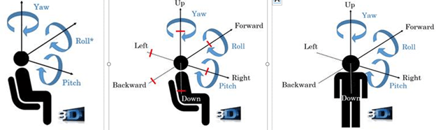
Figure 1 – 3DoF (left), 3DoF+ (centre) and 6DoF (left)
Computer-generated scenes and video are worlds apart
A video is composed of a sequence of matrices of coloured pixels, but a computer-generated 3D scene and its objects are not represented like a video, but by geometry and appearance attributes (colour, reflectance, material…). In other words, a computer-generated scene is based on a model.
Thirty-one years ago, MPEG started working on video coding and 7 years later did the same for computer-generated objects. The (ambitious) title of MPEG-4 “Coding of audio-visual objects” signalled MPEG’s intention to handle the two media types jointly.
Until quite recently the Video and 3D Graphics competence centres (read Developing standards while preparing for the future to know more about how work in MPEG is carried out by competence centres and units) have largely worked independently until the need to compress real world 3D objects in 3D scenes has become important to industry.
The Video and 3D Graphics competence centres attacked the problem using their own specific backgrounds: 3D Graphics used Point Cloud because it is a 3D graphics representation (it has geometry), while Video used the videos obtained from a number of cameras (because they only have colours).
Video came up with a solution that is video based (obviously, because there was no geometry to encode) and 3D Graphics came up with two solutions, one which encodes the 3D geometry directly (G-PCC) and another which projects the Point Cloud objects on fixed planes (V-PCC). In V-PCC, it is possible to apply traditional video coding because geometry is implicit.
MPEG is currently working on two PCC standards: G-PCC standard, a purely geometry-based approach without much to share with conventional video coding and on V-PCC that is heavily based on video coding. Why do we need two different algorithms? Because G-PCC does a better job in “new” domains (say, automotive) while V-PCC leverages video codecs already installed on handsets. The fact that V-PCC is due to become FDIS in January 2020, makes it extremely attractive to an industry where novelty in products is a matter of life or death.
V-PCC seeks to map a point of the 3D cloud to a pixel of a 2D grid (an image). To be efficient, this mapping should be as stationary as possible (only minor changes between two consecutive frames) and should not introduce visible geometry distortions. Then the video encoder can take advantage of the temporal and spatial correlations of the point cloud geometry and attributes by maximising temporal coherence and minimising distance/angle distortions.
A 3D to 2D mapping guarantees that all the input points are captured by the geometry and attribute images so that they can be reconstructed without loss. If the point cloud is projected to the faces of a cube or a sphere bounding the object does not guarantee lossless reconstruction because auto-occlusions (points projected in the same 2D pixel are not captured) may generates significant distortions.
To avoid these negative effects, V-PCC decomposes the input point cloud into “patches”, which can be independently mapped to a 2D grid through a simple orthogonal projection. Mapped patches do not suffer from auto-occlusions and do not require re-sampling of the point cloud geometry and can produce patches with smooth boundaries, while minimising the number of patches and mapping distortions. This is an NP-hard optimization problem that V-PCC solves by applying the heuristic segmentation approach of Figure 2.
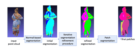
Figure 2: from point cloud to patches
An example of how an encoder operates is provided by the following steps (note: the encoder process is not standardised):
- At every point the normal on the point cloud “surface” is estimated;
- An initial clustering of the point cloud is obtained by associating each point to one of the six planes forming the unit cube (each point is associated with the plane that has the closest normal). Projections on diagonal planes are also allowed;
- The initial clustering is iteratively refined by updating the cluster index associated with each point based on its normal and the cluster indexes of its nearest neighbours;
- Patches are extracted by applying a connected component extraction procedure;
- The 3D patches so obtained are projected and packed into the same 2D frame.
- The only attribute per point that is mandatory to encode is the color (see right-hand side of Figure 3); other attributes, such as reflectance or material properties can be optionally encoded.
- The distances (depth) of the point to the corresponding projection plane are used to generate a gray-scale image which is encoded using a traditional video codec. When the object is complex and several points project to the same 2D pixel, two depth layers are used encoding near plane and far plane (see left-hand side Figure 3 with one single depth layer).
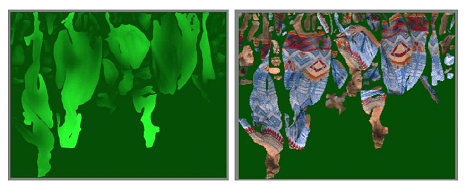
Figure 3: Patch projection
3DoF+ is a simpler case of the general visual immersion case to be specified by part 12 Immersive Video in MPEG-I. In order to provide sufficient visual quality for 3DoF+, a large number of source views need to be used, e.g. 10 ~ 25 views for a 30cm radius viewing space. Each source view can be captured as omnidirectional or perspectively projected video with texture and depth.
If such large number of source views were independently coded with legacy 2D video coding standards, such as HEVC, an unpractically high bitrate would be generated, and a costly large number of decoders would be required to view the scene.
The Depth Image Based Rendering (DIBR) inter-view prediction tools of 3D-HEVC may help to reduce the bitrate, but the 3D-HEVC codec is not widely deployed. Additionally, the parallel camera setting assumption of 3D-HEVC may affect the coding efficiency of inter-view prediction with arbitrary camera settings.
MPEG-I Immersive Video targets the support of 3DoF+ applications, with a significantly reduced coding pixel rate and limited bitrate using a limited number of legacy 2D video codecs applied to suitably pre- and post-processed videos.
The encoder is described by Figure 4.
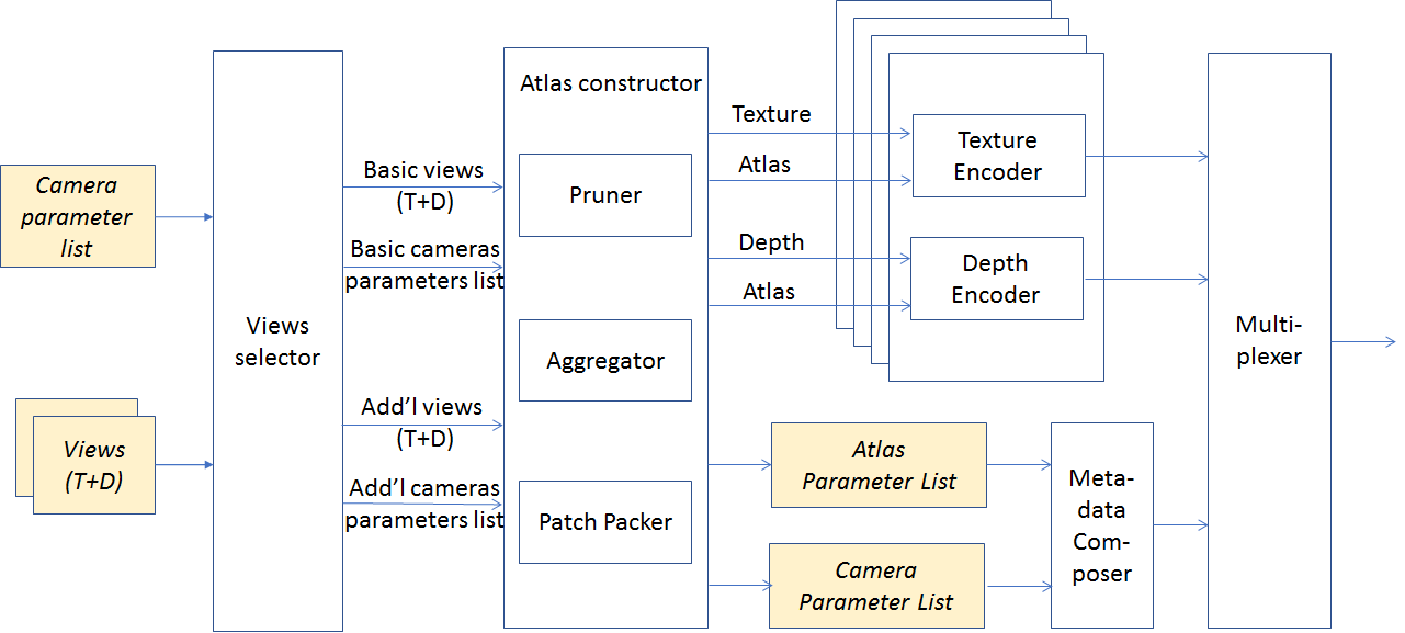
Figure 4: Process flow of 3DoF encoder
An example of how an encoder operates is described below (note that the encoding process is not standardised):
- Multiple views (possibly one) are selected from the source views;
- The selected source views are called basic views and the non-selected views additional views;
- All additional views are pruned by synthesizing basic views to the additional views to erase non-occluded area;
- Pixels left in the pruned additional views are grouped into patches;
- Patches in a certain time interval may be aggregated to increase temporal stability of the shape and location of patches;
- Aggregated patches are packed into one or multiple atlases (Figure 5).
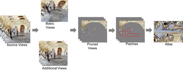
Figure 5: Atlas Construction process
- The selected basic view(s) and all atlases with patches are fed into a legacy encoder (an example of how an input looks like is provided by Figure 6)
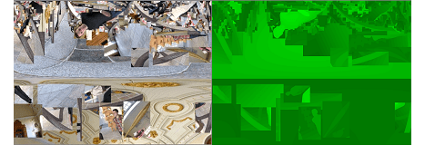
Figure 6: An example of texture and depth atlas with patches
The atlas parameter list of Figure 4 contains: a list of starting position in atlas, source view IDs, location in source view and size for all patches in the atlas. The camera parameter list comprises the camera parameters of all indicated source views.
At the decoder (Figure 7) the following operations are performed
- The atlas parameter and camera parameter lists are parsed from the metadata bitstream;
- The legacy decoder reconstructs the atlases from the video bitstream;
- An occupancy map with patch IDs are generated according to the atlas parameter list and decoded depth atlas;
- When users watch the 3DoF+ content, the viewports corresponding to the position and orientation of their head are rendered using patches in the decoded texture and depth atlases, and corresponding patch and camera parameters.
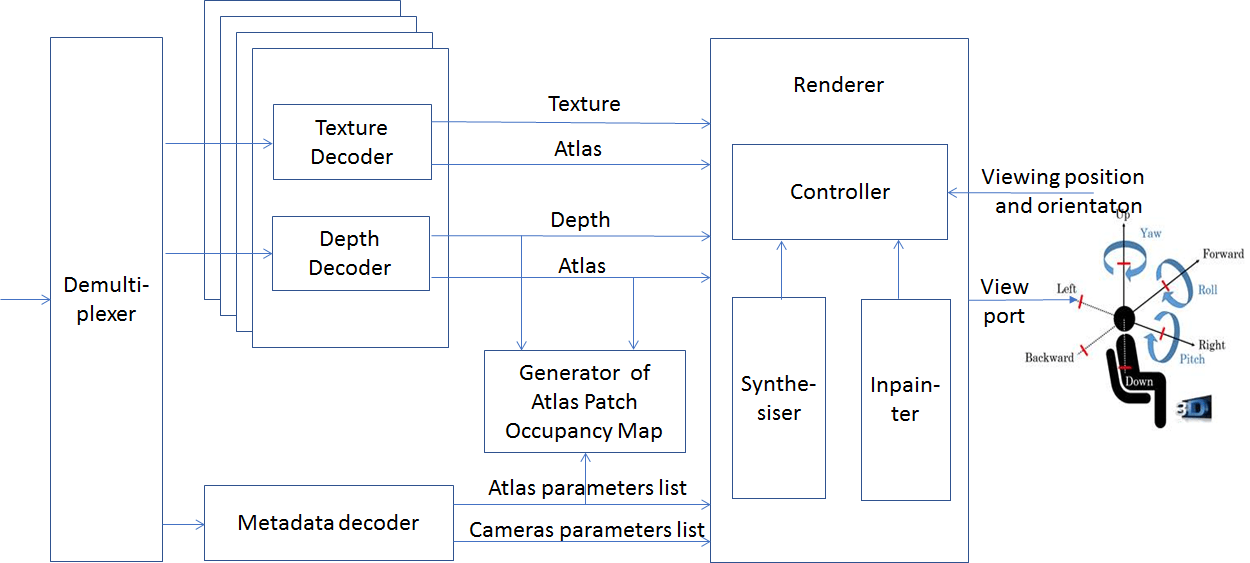
Figure 7: Process flow of 3DoF+ decoder
Figure 8 shows how the quality of synthesised viewports decreases with decreasing number of views. With 24 views the image looks perfect, with 8 views there are barely visible artefacts on the tube on the floor, but with only two views artefacts become noticeable. The goal of 3DoF+ is to achieve the quality of the leftmost image when using the bitrate and pixel rate for the rightmost case.
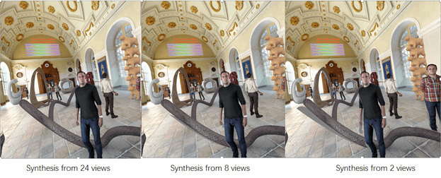
Figure 8: Quality of synthesized video as a function of the number of views
Commonalities and differences of PCC and 3DoF+
V-PCC and 3DoF+ can use the same 2D video codec, e.g. HEVC. For 3DoF+, input to the encoder and output from the decoder are sequences of texture and depth atlases containing patches, which are somewhat similar to V-PCC patches, sequences of geometry/attribute video data also containing patches.
Both 3DoF+ and V-PCC have metadata describing positions and parameters for patches in atlas or video. But 3DoF+ should describe the view ID each patch belongs to and its camera parameters to support flexible camera setting, while V-PCC just needs to indicate which of the 6 fixed cube-faces each patch bonds to. V-PCC does not need metadata of camera parameters.
3DoF+ uses a renderer to generate synthesised viewport at any desired position and towards any direction, while V-PCC re-projects pixels of decoded video into 3D space to regenerate the point cloud.
Further, the V-PCC goal is to reconstruct the 3D model, in order to obtain the 3D coordinates for each point. For 3DoF+, the goal is to obtain some additional views by interpolation but not necessarily any possible view. While both methods use patches/atlases and encode them as video + depth, the encoders and decoders are very different because the input formats (and, implicitly, the output) are completely different.
The last difference is how the two groups developed their solutions. It is already known that G-PCC has much more flexibility in representing the geometry than V-PCC. It is also expected that compression gains will be bigger for G-PCC than for V-PCC. However, the overriding advantage of V-PCC it that is can use using existing and widely deployed video codecs. Industry would not accept dumping V-PCC to rely exclusively on G-PCC.
How can we achieve further convergence?
You may ask: I understand the differences between PCC and 3DoF+, but why was convergence not identified at the start? The answer depends on the nature of MPEG.
MPEG could have done that if it were a research centre. At its own will it could put researchers together on common projects and give them the appropriate time. Eventually, this hypothetical MPEG could have merged and united the two cultures (within its organisation, not the two communities at large), identified the common parts and, step by step, defined all the lower layers of the solution.
But MPEG is not a research centre, it is a standards organisation whose members are companies’ employees “leased” to MPEG to develop the standards their companies need. Therefore, the primary MPEG task is to develop the standards its “customers” need. As explained in Developing standards while preparing for the future, MPEG has a flexible organisation that allows it to accomplish its primary duty to develop the standards that industry needs while at the same time explore the next steps.
Now that we have identified that there are commonalities, does MPEG need to change its organisation? By all means no. Look at the MPEG organisation of Figure 9
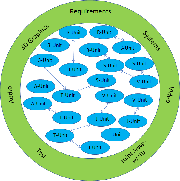
Figure 9 – The flat MPEG organisation
The PCC work is developed by a 3DG unit (soon to become two because of the widely different V-PCC and G-PCC) and the 3DoF+ standard is developed by a Video unit. These units are at the same level and can easily talk to one another now because they have concrete matters to discuss, even more than they did before. This will continue for the next challenges of 6DoF where the user can freely move in a virtual 3D space corresponding to a real 3D space.
The traditional Video and 3D Graphics tools can also continue to be in the MPEG tool repository and continue to supplemented by new technologies that make them more and more friendly to each other.
This is the power of the flat and flexible MPEG organisation as opposed to a hierarchical and rigid organisations advocated by some. A rigid hierarchical organisation where standards are developed in a top-down fashion is unable to cope with the conflicting requirements that MPEG continuously faces.
MPEG is synonymous of technology convergence and the case illustrated in this paper is just the most recent. It indicates that more such cases will appear in the future as more sophisticated point cloud compressions will be introduced and technologies supporting the full navigation of 6DoF will become available.
This can happen without the need to change the MPEG organisational structure because the MPEG organisation has been designed to allow units interact in the same easy way if they are in the same competence centre or in different ones.
Many thanks to Lu Yu (Zhejiang University) and Marius Preda (Institut Polytechnique de Paris) who are the real authors of this article.
Posts in this thread
- On the convergence of Video and 3D Graphics
- Developing standards while preparing the future
- No one is perfect, but some are more accomplished than others
- Einige Gespenster gehen um in der Welt – die Gespenster der Zauberlehrlinge
- Does success breed success?
- Dot the i’s and cross the t’s
- The MPEG frontier
- Tranquil 7+ days of hard work
- Hamlet in Gothenburg: one or two ad hoc groups?
- The Mule, Foundation and MPEG
- Can we improve MPEG standards’ success rate?
- Which future for MPEG?
- Why MPEG is part of ISO/IEC
- The discontinuity of digital technologies
- The impact of MPEG standards
- Still more to say about MPEG standards
- The MPEG work plan (March 2019)
- MPEG and ISO
- Data compression in MPEG
- More video with more features
- Matching technology supply with demand
- What would MPEG be without Systems?
- MPEG: what it did, is doing, will do
- The MPEG drive to immersive visual experiences
- There is more to say about MPEG standards
- Moving intelligence around
- More standards – more successes – more failures
- Thirty years of audio coding and counting
- Is there a logic in MPEG standards?
- Forty years of video coding and counting
- The MPEG ecosystem
- Why is MPEG successful?
- MPEG can also be green
- The life of an MPEG standard
- Genome is digital, and can be compressed
- Compression standards and quality go hand in hand
- Digging deeper in the MPEG work
- MPEG communicates
- How does MPEG actually work?
- Life inside MPEG
- Data Compression Technologies – A FAQ
- It worked twice and will work again
- Compression standards for the data industries
- 30 years of MPEG, and counting?
- The MPEG machine is ready to start (again)
- IP counting or revenue counting?
- Business model based ISO/IEC standards
- Can MPEG overcome its Video “crisis”?
- A crisis, the causes and a solution
- Compression – the technology for the digital age